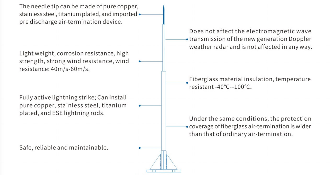
Composite Material Lightning Rod Description:
1. The design of external lightning protection devices for radar station buildings (structures) should be carried out in accordance with the requirements of GB50057 -2010 Class 11 lightning protection buildings
2. Comprehensive measures such as lightning protection equipotential connection, shielding, shared grounding, isolation, reasonable wiring, and surge protection should be taken to protect the internal electrical and electronic systems of the radar station from lightning.
Composite Material Lightning Rod Classification:
1. The classification of radar station lightning protection levels should be determined based on the correction value of the annual average density of lightning-strike ground where the radar station is located, and the value of N should be calculated according to the provisions of appendix A.
2. The classification of lightning protection levels of radar stations is shown in the table
| Annual average density correction value of lightning strikes on the earth N | Lightning protection level |
| Nr>8 | First Class |
| 3<Nr≤8 | Second Class |
| Nr≤3 | Thrid Class |
Requirements For Radar Station Buildings:
1. During the design and construction of the radar station building, the foundation for installing the lightning rod should be reserved on the antenna platform according to the following requirements.
① At least one lightning rod is set upwards during the thunderstorm process
② The lightning rod should be installed evenly and symmetrically on the structural beam or column.
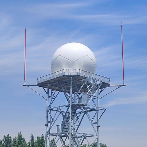
③ The horizontal distance between the vertical projection of the lightning rod and the edge of the radome should not be less than 3m.
2. Equipotential connection terminals should be installed near the lightning rod foundation, near the radar antenna base foundation or antenna tower foundation, and at the entrance where the wave guide and antenna cable enter the building.
Radar Antenna Platform Design
l. lt is recommended to install no less than 3 lightning rods on the radar antenna platform. When the height of the radar antenna cover from the ground is not more than 15m, no less than 2 lightning rods can be directly installed on the ground. The protection range of the lightning rod shouId be determined using the rolling ball method, and the distance from the boundary of the protection range to the edge of the radar radome and other equipment on the antenna platform should not be less than 0.5m
2. The support rod of the lightning rod located below the zero degree lower edge of the radar antenna elevation angle should be made of steel pipe, and the support rod of the lightning rod above should be made of high-strength fiberglass steel pipe. The wall thickness and strength of the steel pipe and fiberglass steel pipe should meet the requirements of local maximum wind speed, maximumicing thickness, and other meteorological conditions
3. Multi core copper stranded wires should be installed as down conductors in glass fiber reinforced plastic pipes and steel pipes, with a cross-sectional area of no less than 50mm. lt is advisable to install a lightning strike counter on the support rod of one of the lightning rods
4. For radar stations located at the top of mountains, lightning rods or lightning wires should be installed along the periphery of the radar station based on the local mountain conditions and lightning activity patterns.

Maintenance And Management
The lightning protection device should undergo regular testing and periodic maintenance. Before the thunderstorm season every year, the operation and aging of lightning protection devices should be comprehensively tested. After the thunderstorm season ends, the working status of power SPD, backup protection device, and signal SPD should be checked. Theannual inspection report should be properly kept, and any safety hazards or issues with lightning protection devices should be promptly eliminated

