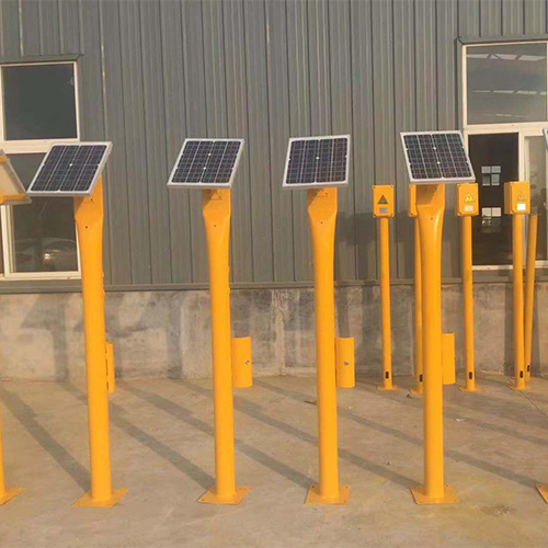
Test Station Cathodic Protection Introduction:
Test station cathodic protection is suitable for cathodic protection of buried metal pipelines in different industries such as natural gas, liquefied petroleum gas, petroleum, refined oil, artificial gas, chemical industry, water conservancy and water supply, etc. It is also applicable to the cathodic protection of underground structures in the city, such as buried metal pipeline network, oilfield pipeline network and long-distance metal buried pipeline. Special specification test piles can be customized according to customers’ requirements.
Test pile is a kind of accessory equipment specially used for cathodic protection of pipeline with potential test probe to test the protected pipeline.It is used to measure the cathodic protection current, potential, grounding resistance of the main distribution point of cathodic protection system, the electric insulation performance of the insulation device, and also can be used for the test of covering layer picking up leakage and AC/DC interference. Measuring device for monitoring the operation status of anode and other important parameters.
The anode is made of metal material with negative potential, when it is connected with the protected pipeline, it will dissociate itself preferentially, thus relieving the corrosion of the pipeline, so it is called sacrificial anode.Sacrificial anode should have enough negative stabilizing potential to maintain a large enough driving voltage, and at the same time have a large theoretical generation of electricity, but also have a high and stable current efficiency.
Test Station Cathodic Protection Multifunctionality:
Potential test pile: mainly used for detecting protection potentials
Sacrificial Anode Test Pile: Used to connect the sacrificial anode and measure the performance parameters of the sacrificial anode.
Current Test Pile: Measure the current in the tube.
High potential magnesium anode use production, products in line with ASTM97-98 standard using a specific process, the anode has the electrochemical properties, in the process of cathodic protection, the anode consumption is uniform, so there is a longer service life.
In actual use, the actual measured working potential is between -1.8v and -1.85v, thus providing effective protection to the target structure.High potential magnesium anodes are recommended for soils with a resistivity greater than 8000ohm.cm.
There are two kinds of test piles with full height of 3 meters or 2 meters and diameter of 0.1 meters. After the latest improvement of the test pile has a better anti-corrosion and anti-ultraviolet anti-aging performance. The test piles are made of stainless steel for the test ports and door shafts. The test piles are equipped with rainproof eaves to prevent the intrusion of rainwater. The test pile inspection door is equipped with a special opening key to prevent abnormal opening. Test piles are used for the detection of cathodic protection parameters. It is used to measure the cathodic potential, current, grounding resistance of the main distribution points of the cathodic protection system and the electrical insulation performance of the insulating device. Measuring device for monitoring important parameters such as anode movement status. The device has 6, 8 and 10 terminals, which can be conveniently composed of potential, current, sacrificial anode, insulation performance test pile or cross-pipe test pile according to the specific requirements of the design unit. The test pile consists of pile body, test terminal board, test wire and nameplate.
Test Station Cathodic Protection Construction:
During construction, the cathodic protection test device should be installed at the same time with other cathodic protection systems. When installing the test device, the position should be set along the direction of the protected pipeline, and the distance between two test devices adjacent to each other should be between 1km and 3km. If the pipeline passes through the city, town or industrial park, the distance between the test devices should not be more than 1 kilometer, and if the test is carried out in the area affected by the interference of stray currents, the distance between the test devices should be appropriately encrypted.
The environment in which the test devices are generally placed include: cross or parallel section of the protected pipeline and AC or DC electrified railroad; the place of installing insulated joints; the place of connecting to the grounding system; the place of installing metal casing; the place where the protected pipeline is connected with other pipelines or structures; the place where the auxiliary specimen and grounding device are connected; the place where the pipeline crosses with the surrounding roads or embankments; the place where the pipeline passes through the railroads or the flowing water; the place where the pipeline is connected with external metal pipes; the place where the test devices are connected to the external metal pipes or structures. Where the pipeline crosses surrounding roads or dams; where it crosses railroads or flowing water; where it is adjacent to external metal structures, etc. When installing the test device at least two cables are connected to the protected pipeline, and the cables used should be differentiated by color, or make other signs to distinguish, and to achieve uniformity throughout the line.

